Reducing the production cost per ton of steel is an effective way for steel companies to improve their competitiveness. Minimizing controllable heat loss within the ladle is an effective measure to reduce production costs and save energy. By covering the ladle and using corresponding cover-opening devices, radiative heat loss is significantly reduced. The ladle is covered throughout its entire lifecycle, from converter to ladle refining to continuous casting, slag removal, and hot repair platform, significantly reducing heat loss. However, due to differences in existing equipment at various workstations, there is no standardized structure for the ladle covering device, requiring design tailored to specific circumstances. The design must ensure orderly operation at each workstation while maximizing equipment versatility for easy maintenance and cost reduction. Based on existing cover-opening devices, the converter steelmaking plant has adapted and incorporated its own plant structure and equipment specifications to design a comprehensive ladle covering system.
Design Scheme Selection
1.1 Factory Layout
The converter plant has three steelmaking areas with an annual steel output of over 10 million tons. Taking the first converter steelmaking area as an example, the plant has three 150-ton converters, one double-station LF/CAS refining furnace, one double-station LF refining furnace, one double-station RH refining furnace, and three continuous casting machines.
The ladles are transported between each workstation by overhead cranes. The main routes within the plant are as follows:
Converter → Continuous Casting → Slag Removal → Ladle Tilting Platform;
Converter → LF Furnace → Continuous Casting → Slag Removal → Ladle Tilting Platform;
Converter → RH Furnace → Continuous Casting → Slag Removal → Ladle Tilting Platform;
Converter → LF/CAS Furnace → Slag Removal → Ladle Tilting Platform;
Converter → LF/RH Furnace → Slag Removal → Ladle Tilting Platform.
After the overhead crane lifts the steel ladle to the converter, IF furnace, LF/CAS furnace, or RH furnace, the ladle car is transported to the designated location via rails. The rails for the converter and RH furnace are parallel, while those for the LF furnace and LF/CAS furnace are perpendicular to the rails for the converter.
1.2 Scheme Determination
Currently, there are various ladle-covering devices used throughout the entire ladle-covering process, including mobile pin-type ladle-covering devices, hydraulic lifting/telescopic ladle-covering devices, rotary ladle-covering devices, and suspended mobile ladle-covering devices. Because the rail direction of the converter and RH furnace is perpendicular to that of the LF and LF/CAS furnaces, and considering factors such as plant space, the aforementioned ladle-covering devices cannot be used at all workstations. The design primarily considers equipment reliability while maximizing equipment standardization to reduce maintenance workload, increase equipment utilization, and lower costs. Therefore, the converter and RH furnaces use a hoist lifting device, while the LF and LF/CAS furnaces use a hoist lifting and lateral movement device, maximizing equipment uniformity.
Design of a ladle cover throughout the process
The main equipment of the ladle covering system includes: ladle cover, cover application and removal machine, and other auxiliary equipment. The design of the system directly affects its operational efficiency. The design prioritizes operational efficiency and ensures equipment standardization as much as possible.
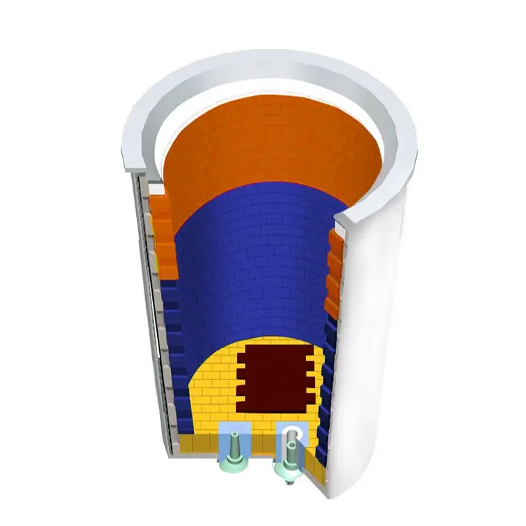
2.1 Steel Ladle Cover Design
The ladle cover is a crucial component of the ladle covering system. After practical testing, a U-shaped connection was selected between the ladle cover and the ladle. Through stress analysis of the ladle cover during the entire ladle operation process, the U-shaped structure was optimized, as shown in Figure 1.
A 140mm thick layer of refractory material is poured inside the ladle cover to achieve insulation and protect the cover structure from severe deformation due to high temperatures. Appropriate observation holes and sand drainage holes are pre-drilled in the ladle cover to ensure that the original process can be completed without opening the cover after it is put on. The ladle cover also features three hanging lugs; the hooks of the cover-opening machine work in conjunction with these lugs to complete the covering and opening actions. In case of abnormal situations requiring the use of a spare lifting device to remove the ladle cover, which would disrupt production, a spare hanging lug is designed at the center of gravity of the ladle cover. This spare lug is located at the extension line of the ladle cover’s center of gravity and has a smooth, rounded guide section. This spare lug has an automatic centering function, preventing the ladle cover from tilting significantly during lifting and eliminating the need for a dedicated offline lifting device.
2.2 Lifting Device Design
Currently, lifting devices include pinion type, moving pinion type, hydraulic lifting/telescopic type, rotary type, and suspended moving type. The most commonly used lifting devices are the fixed pinion type and the moving pinion type. This structure allows for quick capping and uncapping, but the significant impact can negatively affect equipment lifespan and requires considerable space. The rail direction of the Liuzhou Steel converter and RH furnace is perpendicular to the rail direction of the LF furnace and LF/CAS furnace. The above structural methods can only meet the requirements of some processes, thus requiring different lifting devices, which does not conform to the principle of using standardized equipment as much as possible. Considering the structural characteristics of the Liuzhou Steel converter steelmaking plant, the converter and RH furnace adopt a hoist lifting ladle capping device, while the LF furnace uses a hydraulic lateral moving hoist lifting ladle capping device. This solution only adds a hydraulic lateral moving structure to the LF furnace; the other components use a standardized structure.
(1) Hoisting lifting ladle with cover opening device for converter and RH furnace
The ladle cover-adding and unaddressing device for converters and RH furnaces only needs to perform the lifting and lowering actions of adding and removing the cover. The design employs a winch system, with a three-phase asynchronous motor as the power source; the motor’s forward and reverse rotation achieves the lifting and lowering actions. The ladle cover design uses three hooks, therefore the winch drum needs to simultaneously wind and unwind three wire ropes to ensure the stability and synchronization of the cover-adding and unaddressing. A specially designed winch drum is required to meet these requirements. The designed winch-type ladle cover-adding and unaddressing device is shown in Figure 3. As shown in Figure 3, when the winch stops the hook of the lifting frame in the appropriate position, the ladle car can move forward or backward to complete the hooking and unhooking of the lifting frame hook and the ladle cover hook.
(2) LF furnace hydraulic transverse hoisting lifting ladle cover opening device
Because the rail direction of the Liuzhou Iron and Steel converter and RH furnace is perpendicular to the rail direction of the LF furnace and LF/CAS furnace, the LF furnace cannot achieve ladle cover lifting and unlifting using only a winch-type lifting mechanism. A lateral movement is needed in the direction perpendicular to the guide rail. The design employs a lateral movement trolley device, powered by hydraulic pressure. The extension and retraction of the hydraulic cylinder enables the lateral movement trolley to move forward and backward. Therefore, only the existing winch-type ladle cover lifting and unlifting device needs to be installed on the lateral movement trolley. The hydraulic lateral movement winch-type ladle cover lifting and unlifting device is shown in Figure 4. As shown in Figure 4, when the winch stops the hook of the hoist in the appropriate position, the ladle car must also stop in the appropriate position. At this time, the hydraulic cylinder controls the entire lateral movement trolley to move forward or backward to complete the hooking and unhooking of the hoist hook and the ladle cover lug.
Implementation effect
The implementation of full-process ladle covering at Liuzhou Iron and Steel Group (Liugang) was carried out with meticulous planning of each step, without affecting existing production. The project began with the installation of hoist-type ladle cover-opening devices at three converters, enabling direct connection from converter to continuous casting, achieving the first phase of work and demonstrating good cooling effects. Building on this, hoist-type ladle cover-opening devices were installed at two RH furnaces, enabling the converter-RH furnace-continuous casting process. Finally, hydraulically lateral hoist-type ladle cover-opening devices were installed at two LF furnaces and two LF/CAS furnaces, enabling the converter-LF furnace-continuous casting, converter-LF/CAS furnace-continuous casting, and converter-LF/RH furnace-continuous casting processes. Data collection and comparison before and after the full-process ladle covering project were conducted to analyze its feasibility. During tapping, under the same conditions, simply covering the ladle for insulation reduced the average temperature drop of molten steel by 8.3℃, demonstrating a significant cooling effect. After achieving good cooling results in Converter Steelmaking Zone 1, the corresponding full-process ladle covering project was immediately implemented in Converter Steelmaking Zones 2 and 3. Currently, the full-process ladle covering project has been completed and has achieved good cooling results.
Liuzhou Iron & Steel’s Converter Steelmaking Plant systematically implemented the full-process ladle covering project. Based on the actual conditions of the Converter Steelmaking Zone 1 plant, a full-process ladle covering device was designed. Specifically, a hoist-type ladle covering device was used in the converters and RH furnaces, while a transverse hoist-type ladle covering device was used in the LF furnace. After achieving good results, the project was extended to other areas. Currently, the full-process ladle covering project is operating well, with significant cooling effects, greatly reducing the production cost of the entire smelting process, and improving the smelting environment.