1.Check the furnace body’s operating condition
- Requirements
This includes the inspection and treatment of the furnace body yoke, hydraulic system, water cooling system, induction coil and its insulating varnish, coil paste, and empty furnace test.
(1) Visually inspect the furnace body yoke fastening screws for looseness. If loose, they must be tightened. At the same time, any splashed or adsorbed iron filings on the yoke should be removed.
(2) Turn on the hydraulic switch and rotate the furnace body. If the furnace body cannot rotate normally, it should be repaired immediately.
(3) Turn on the water cooling system pump and check for water leakage in each connecting pipe. If any leakage is found, the water cooling pipes should be tightened or replaced immediately to ensure the normal operation of the water cooling system.
(4) Check the integrity of the furnace body coil insulating varnish and the coil paste between the upper structure and the coil. If there is any damage, it should be filled with special insulating varnish and coil paste. There must be no excess metal adhering to the energized coil. When using coil slurry for filling, it must be allowed to air dry naturally for 24-48 hours, or after air drying for 12 hours, it can be placed in a crucible mold and baked at a low power of approximately 10kW for 1-2 hours to remove moisture and prevent short circuits between turns.
(5) Check the gaps between the upper components and whether the upper components and coils are smoothly connected. If the gaps are too large, plastic material can be used to fill and smooth them.
(6) Empty furnace test: After powering on the empty furnace, maintain full power for 2 minutes. At this time, the furnace current is at its minimum and the furnace pressure is at its maximum. Carefully check the furnace pressure. Only after the furnace pressure is normal can subsequent knotting operations be carried out.
- Purpose
Through the above steps, the aim is to minimize the need for necessary or difficult-to-judge furnace shutdowns and dismantling due to unforeseen events such as loosening of furnace body magnetic yoke fastening screws, grounding wires, furnace body insulation (inter-turn short circuits and induction coil adsorption of iron pellets), leakage, moisture inherent in the filling coil rubber, and failure of the upper furnace body to smoothly transition with the coil, affecting the natural shrinkage of the furnace lining and causing cracks. This ensures the normal use of the furnace lining and extends its service life.
2.Knotting tools preparation
The following tools are generally used for dry lining of medium-frequency induction furnaces: 6 degassing forks (3 long and 3 short), 1 tamping side hammer, 1 handheld vibrator, and 2 pneumatic vibrators, as shown in the diagram below.
- Degassing Forks
The degassing forks have parallel teeth at the bottom, with sharper tips. They are mainly used to evenly and compact the furnace lining material added around the crucible mold, and to loosen the top surface of the previous layer of lining before adding the next layer. During the lining process, air is manually removed from the lining material to achieve pre-compactment. The length of the fork teeth should be greater than or equal to the height of each layer of lining material added. To ensure the electric vibrator can transmit impulse to the junction of the previous and current layers without affecting efficiency, a tooth length of 100-120mm is suitable. Before furnace construction, the fork teeth must be repeatedly inserted into the molding sand manually to remove rust and prevent rust from falling into the lining and affecting its quality.
- Tamping Hammer
The tamping hammer is similar in shape and size to the crucible’s circumference. A specially designed tamping hammer is used to compact the furnace lining surface, ensuring the knotted furnace wall has a high density (above 2.1 g/cm³). It can also be used in conjunction with a vibrator for areas on slopes where manual compaction of the lining is difficult.
- Handheld Vibrator
This vibrator generates vibration when powered on, primarily used for compacting the lining material on slopes.
- Pneumatic Furnace Construction Machine
Pneumatic furnace construction machines are mainly divided into vibrators for the furnace walls and vibrators for the furnace bottom. Their main function is to pneumatically compact the furnace lining material after the charge has been added. This reduces uneven compaction caused by variations in manual degassing force, ensuring the overall uniformity and density of the lining material, thus extending the furnace lining’s service life.
3.Crucible Mold
The crucible mold must possess sufficient strength during construction and sintering. It must not deform during construction to ensure the transmission of vibrational energy to the furnace lining material, thus compacting it. It must not melt before the hot surface of the lining material forms during sintering, and it must not be affected by magnetic fields, resulting in localized deformation or melting.
If any of these situations occur, the lining material will fill the gaps created by mold deformation, reducing the lining density and consequently affecting its strength and shortening its lifespan.
Based on practical experience, when using an electric vibrator to vibrate the crucible mold for a 6-ton furnace, the original 6mm steel plate crucible mold was improved to 10mm. For a 20-ton medium-frequency induction furnace, using 10mm thick A3 steel plate welded together ensures the crucible mold has high strength and is not easily deformed during vibrator hammering. Furthermore, the crucible mold effectively transmits vibrational energy to the lining material, achieving the goal of compacting the lining and thus ensuring its strength and service life.
The structural characteristics of the crucible mold directly affect the lifespan of the furnace lining. Therefore, the following aspects should be considered:
- Crucible Mold Body Circumference
The main circumference of the crucible mold can be designed as thinner at the top and thicker at the bottom with an angle, or as a straight cylinder without an angle. For those with an angle, it is generally advisable to control it within 1~4°. The size of a straight cylindrical crucible mold should be greater than or equal to the safe thickness of the thinnest part of the furnace lining.
- Determining the Crucible Mold Height
Generally, the length of the crucible mold is considered to be the distance from the bottom furnace lining thickness to the highest point of the furnace body. However, in practice, the following factors should be fully considered: melting efficiency, smelting materials, the erosion areas of the furnace lining in the medium-frequency furnace, and the furnace cover.
Under normal circumstances, the bottom erosion of medium-frequency furnaces producing gray iron or ductile iron is not significant (approximately 30~50mm). The bottom edge can be used as a reference point, pressing down on the upper edge of the bottommost induction coil.
Simultaneously, the overall height of the crucible mold should be the vertical distance from the top plane of the furnace lining to the plane of the furnace edge, plus a height approximately 50mm above the furnace edge. This height is beneficial for the subsequent sintering of the furnace lining with molten iron. The specific height should be determined so as not to interfere with closing the furnace lid.
- Dimensions and Shape of Corners
This area is most prone to “elephant foot” defects, and because it is located at the bottom of the furnace lining and is constantly encased in molten iron, it cannot be observed. Therefore, it must be designed accordingly.
When the slope angle is too large, it can increase the furnace lining thickness, but it can easily lead to loose lining knots and more severe mechanical damage during charging. However, by following the principle of “small slope angle and large length,” the furnace lining at this point is easier to knot tightly later. During melting, the strong resistance to impact, corrosion, and pressure at the slope of the furnace lining can be fully utilized, thus avoiding “elephant foot” defects and improving the service life of the furnace lining.
- Drilling Vent Holes and Bottom Shape
Small holes in a diamond pattern should be drilled at intervals of 200-300mm on the bottom, slope, and side walls of the crucible mold. This facilitates the drainage of moisture from the furnace lining material during the baking stage, increases resistance, and improves the heating and baking effect.
The diameter of the holes should ideally be 3mm. Too small a diameter will result in poor venting, while too large a diameter will cause a large amount of furnace lining powder to spray out during furnace vibration.
The bottom plane of the crucible mold should not be concave; it should ideally be horizontal, or protrude about 1mm outward from the center. This prevents air gaps and structural stress at the bottom after furnace construction, which could lead to “bottom bursting” during baking and sintering.
- Other
All welds must be ground smooth and free of welding flux and sharp corners. The outer diameter tolerance and concentricity of the crucible mold should be controlled within 5mm. The crucible mold must be shot-blasted to remove rust before use.
4.Install furnace bottom grounding probe
The medium-frequency induction furnace is equipped with a professional early warning system for furnace leakage and through-furnace damage. This is a crucial safety barrier and cannot be neglected. Before furnace construction, the usability of the grounding probe must be ensured.
- Lift the furnace bottom push-out block to the furnace bottom, align it with the grounding probe hole, and place it stably.
- Insert the grounding probe into the grounding probe hole and rotate the furnace body to the appropriate position.
- Connect the furnace body grounding wire to the grounding probe, generally using at least two screws to ensure the grounding wire is stable and does not come loose.
- Use a testing tool to connect the probe and the furnace platform to check if the GLD connection is normal. Only if it is normal can the subsequent work of knotting the furnace lining proceed.
- Bend the stainless steel wire on the probe 300mm to prepare for knotting the furnace bottom.
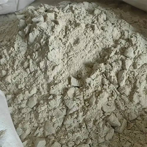
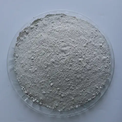
5.Knotting materials, furnace body cleaning preparation
Before knotting, the supplied furnace lining material must be blown and inspected, and the furnace platform must be cleaned.
- Blow away dust from the packaging tape of the furnace lining material and check that the material grade and specifications meet the requirements. During hoisting, no metal objects, magnetic materials, packaging tape, sawdust, sand, cigarette butts, or other debris must be mixed in, as these can melt at high temperatures, forming voids and cracks, leading to iron seepage, shortening the furnace lining life, and affecting its quality.
- During knotting, a designated person must hoist the material, open the plastic bag seal, and check for damage or dampness. If damage, dampness, or clumping is found, the material should be discontinued, or the damp lining material should only be used for repairing the burner nozzle; otherwise, it may easily cause localized cracking and peeling of the furnace lining.
- Clean the furnace chamber, furnace cover, and surrounding area of the furnace platform of any metal debris, keeping the work area clean. Empty any items from work clothing pockets, especially keys, to prevent them from falling into the furnace charge and causing accidents.