
As a core piece of equipment in steelmaking, the quality of the converter lining construction directly determines its service life and production efficiency. This solution combines advanced domestic and international experience to construct a systematic solution from three dimensions: material selection, process optimization, and quality control. It focuses on addressing the differences in working conditions in different parts and proposes a full-process technical system of “zonal material selection + precise construction + dynamic maintenance”.
1.Material system and performance adaptation
(I) Selection of working layer materials
Slag Line Zone: MT18A magnesia-carbon bricks (MgO≥88%, C≥14%) are used, with a slag erosion resistance index 35% higher than ordinary magnesia-carbon bricks, suitable for areas with a slag erosion rate >2mm/furnace service.
Charging Side: Antioxidant magnesia-carbon bricks with 0.5% added aluminum powder are used, achieving a residual strength retention rate of 82% after a 1600℃×3h thermal shock test.
Taphead: Integral cast magnesia-carbon sleeve bricks are used, with an inner diameter tolerance controlled within ±0.5mm, filled with high-alumina ramming material to ensure no leakage after more than 2000 thermal cycles.
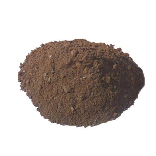
Applications of Amorphous Materials
The annular zone of the furnace cap uses Al₂O₃-MgO self-flowing castable with a construction fluidity ≥220mm and a bulk density of 2.95g/cm³ after drying at 110℃ for 24 hours.
The permeable bricks are surrounded by corundum-based quick-drying anti-seepage material with a penetration depth ≤1mm/24h, effectively blocking the steel seepage channels.
(II) Optimization of Permanent Layer Materials
The fired magnesia bricks use fused magnesia aggregate (MgO≥97%) with an apparent porosity ≤16%, and a linear shrinkage rate of only -0.12% after firing at 1550℃ for 3 hours.
A 5mm thick Hru ceramic fiber paper expansion joint is installed between the permanent layer and the working layer, with a compensation coefficient of 0.8%/1000℃, to avoid thermal stress concentration.
2.Standardized construction process
(I) Construction Preparation
Environmental control
A temperature and humidity monitoring system should be installed in the masonry area. Construction can only proceed when the ambient temperature is above 5℃ and the relative humidity is below 70%.
Refractory bricks must undergo preheating treatment at 200℃ for 24 hours, with a moisture content ≤0.3%.
Equipment calibration
The furnace center is positioned using a laser rangefinder, with an error ≤ ±1mm.
The vibratory rod amplitude is controlled at 0.5±0.05mm, and the frequency is 12000 times/min, ensuring the compaction density of the ramming material is ≥2.8g/cm³.
(II) Sectional Masonry Technique
Furnace bottom construction
The permanent layer is constructed using a cross-hatching method, with upper and lower layers of magnesia bricks staggered at 90°, and mortar joint thickness ≤1mm.
During installation of the permeable bricks, a laser alignment system is used, achieving a positioning accuracy of ±0.2mm. The area around the tailpipe is filled with silicon carbide sealant.
Furnace body construction
The working layer employs a “spiral ascent method,” with at least three bricks misaligned in each ring. Expansion joints are arranged in a “three horizontal, four vertical” pattern, with spacing controlled between 1.2-1.5 meters.
The trunnion section utilizes prestressed anchoring technology, with dovetail grooves cut into the refractory brick surface and 8mm diameter 310S stainless steel anchors inserted.
Furnace cap construction
An adjustable arc-shaped template is used to ensure that the roundness error of the conical section is ≤3mm/m.
The furnace mouth pressing brick material uses magnesia-based dry vibratory material, tamped in three layers, with each layer having a compaction coefficient ≥0.95.
(III) Control of Key Nodes
Transition zone processing
Custom-made irregularly shaped bricks are used for the arc transition section between the molten pool and the furnace bottom, with a curvature radius deviation of ≤±2mm.
A 2mm thick phosphate binder is applied between the permanent layer and the working layer to form a transitional bonding layer.
Oven Curve Optimization
A three-stage heating method is adopted:
Low-temperature stage (room temperature – 300℃): heating rate ≤ 15℃/h, constant temperature for 8 hours to remove free water;
Medium-temperature stage (300-800℃): heating rate ≤ 25℃/h, constant temperature for 12 hours to complete the decomposition of crystal water;
High-temperature stage (800-1200℃): heating rate ≤ 35℃/h, constant temperature for 24 hours to achieve sintering densification.
3.Quality control system
(I) Process Monitoring
Infrared Thermal Imaging Inspection
Surface temperature is scanned after each layer of masonry is completed. Areas with a temperature difference >15℃ require local rework.
The furnace shell temperature is monitored in real time during the furnace drying process. The emergency cooling system is activated when a local hot spot exceeds 250℃.
Ultrasonic Flaw Detection
Spot checks are conducted on key parts (permeable bricks, steel tapholes). Defects with an equivalent diameter >φ3mm are considered unqualified.
(II) Acceptance Standards
Dimensional Accuracy
Furnace body verticality deviation ≤ 5mm/m, total height error ≤ 15mm.
Expansion joint width deviation ≤ ±1mm, straightness error ≤ 2mm/m.
Physicochemical Properties
Working layer apparent porosity ≤ 18%, compressive strength ≥ 80MPa (1400℃×3h).
Permanent layer load softening temperature ≥ 1650℃ (0.2MPa).
4.Innovative technology applications
3D Printed Prefabricated Parts
For complex structures (such as breathable brick bases), Al₂O₃-ZrO₂-C prefabricated parts are used, achieving a dimensional accuracy of ±0.1mm and improving installation efficiency by 40%.
Intelligent Temperature Control System
Embedded fiber optic sensors monitor the temperature gradient in real time, automatically adjusting the heating power when ΔT > 50℃/h.
Nano-Modification Technology
Adding 0.3% nano-SiO₂ to the castable increases the thermal shock resistance (TSP) from 250 cycles to 400 cycles (1100℃ water cooling).
5.Converter drying scheme
After placing firewood and coke into the converter, heat it for 5-8 hours. When the temperature reaches 1200-1300℃, molten iron can be added for a trial firing. When smelting the first batch of steel, only molten iron should be added; scrap steel is not allowed.
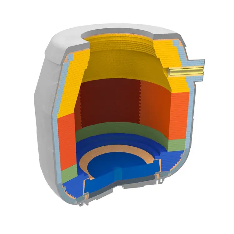
6.Furnace type optimization
Based on CFD simulation, the furnace lining thickness distribution was adjusted, increasing the slag line thickness by 15% and reducing the trunnion thickness by 10% compared to traditional designs.
This solution, through collaborative innovation in materials, processes, and maintenance, extends the converter lining life to over 8000 heats, reduces refractory material consumption per ton of steel to 0.8 kg/t, and lowers overall maintenance costs by 35%. In practical applications, dynamic adjustments based on specific furnace parameters are necessary. It is recommended to conduct laser scanning inspection every 50 heats to establish a 3D digital twin model to guide precise maintenance.
BOF Furnace