
The signal is fed back to the control system through the detector, which controls the digital electric cylinder and linear slide actuator to effectively control the molten steel flow in the tundish.
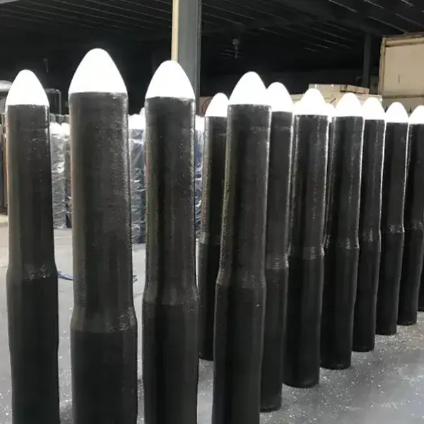
1.Monoblock Stopper
1.1Functions of Stoppers
During continuous casting, they stabilize the steel flow, reduce impact and agitation on the mold, stabilize pouring operations, even out the temperature and composition of the molten steel, and allow deoxidation products and non-metallic inclusions to float. They also act as a buffer during ladle changes during multi-furnace continuous casting. They distribute the steel flow on multi-strand continuous casting machines and provide a shutoff protection during online baking and accidents.
1.2Stopper Installation and Precautions
Properly install the stopper to ensure smooth lifting and lowering during pouring. Avoid excessive force, which can cause the stopper to break, or failure to close during pouring.
Before installation, remove any stuck steel and slag from the beam. Inspect the inside and edges of the nozzle brick holes for debris. Be sure to blow clean the area around the nozzle bricks with compressed air. Inspect the stopper for cracks and other defects. Handle the stopper with care during transportation and assembly, avoiding collisions. Remove the stopper from the drying chamber and secure it to the lifting mechanism beam with a nut and washer.
During assembly, ensure the threaded graphite sleeve in the threaded hole on the stopper rod head is installed flat. After inserting the bolts, ensure tight contact and no looseness. After tightening the bolts, apply an even layer of mastic to the stopper rod head, cover with a metal plate, tighten the nut, and allow it to rest naturally for 4-8 hours. Assembly is performed in a dedicated location, using a vertical assembly system. The stopper rod must not be placed horizontally. For assembly systems, check the adhesive between each sleeve brick to ensure it is intact and free of cracks or looseness.
After assembly, use specialized tools to hoist the stopper rod to its installation location, aligning the mounting holes. Install only the upper bolts, aligning them against the support arm. Tighten the retaining nut and connect the argon gas line. Check the lift mechanism for flexibility and ensure sufficient sliding distance during lifting and lowering to prevent the steel flow from being too loose or too inadequate. Install the stopper rod vertically on the nozzle, rotating it forwards and backwards to gently grind the contact area between the stopper rod and the nozzle to ensure a tight fit. Tap the bottom of the support arm to secure the stopper rod.
2.Control mechanism
The control system, comprised of electric cylinders, drivers, and electronic control systems, was designed to withstand the high temperatures, strong vibrations, and high interference conditions encountered on-site. However, the CNC electric cylinder’s control of the stopper rod is achieved through an actuator, which affects the accuracy of the entire control system. The actuator’s performance has a complex and multifaceted impact on the control system, including clearance, wear, alignment, mounting method, high temperatures, and molten steel impact.
3.Actuator
3.1Components
The actuator consists of a main frame, lifting rods, linear guide rails, protective covers, crossbeams, safety locks, and a manual rotary lever. It is a critical component in the tundish stopper rod automatic control system and directly impacts control accuracy.
3.2Working Conditions
The actuator is mounted on the outer wall of the tundish via the frame’s base. The lifting rod utilizes linear guide rails, effectively reducing friction and improving positioning accuracy. The electric cylinder is embedded within the actuator frame, as shown in Figure 2. This allows the moving parts of the electric cylinder to be directly connected to the lifting rod, reducing mechanical transmission errors and ensuring high control accuracy. Protected by the integral frame, the electric cylinder boasts a compact structure, providing dust and collision protection while avoiding exposure to high-temperature, fumes-prone environments such as drying tundishes. This extends its service life and reduces operating costs.
The safety lock is an electric cylinder locking device that secures the cylinder in the vertical position. The manual rotary lever is a manual control device for the stopper rod movement. Workers can operate it from a distance from the ladle using a long-handled sleeve. It is an indispensable part of the actuator.
4.Detector
The signal is fed back to the control system through the detector, which controls the digital electric cylinder and linear slide actuator to effectively control the molten steel flow in the tundish, so that the molten steel level in the continuous casting crystallizer is stable, achieving the automatic control effect of constant liquid level and constant casting speed.
5.Common fault analysis and solutions
The main factors affecting the life of the stopper actuator are prolonged tundish online baking time and excessively high temperatures; and the slide rails losing their effectiveness due to sustained high temperatures in the operating environment.
Adding a cooling gas pipe connection to the front cover ensures efficient inert gas flow during operation. Adding a heat shield and asbestos to the main frame base plate connected to the tundish’s outer wall also extends the life of the slide rails by ensuring they operate within their rated temperature range.